If you’ve been woodworking for some extended length of time and have had the opportunity to use a wide range of hand planes, you may have noticed that there’s more to the cap iron than just keeping the cutting iron assembly tight against the frog. Sure, that is their function, but you’ll eventually experience the difference: on some planes, you can loosen the lever cap without even looking and you feel in total control because of the smooth operation.
On others, however, it’s a little more intense, and I say this with a bit of humour but there’s a very real element of truth to it: you grip the lever firmly, with the intention of releasing the pressure smoothly, yet as hard as you try, BAM! It rattles all over the place and produces such a commotion that it makes you jump. Well, call me a little obsessive, but there are perfectly functional planes I’ve shied away from just because of the feeling of unrest it brings to a quiet, peaceful evening in the workshop. The clip below of me trying to secure a lever cap shows what I mean.
Anyway, after observing the phenomenon several times over ten-plus years of woodworking, I only just recently stopped to intentionally analyse the problem at hand.
The key lies in the shape of the internal corner of the actual lever on the lever cap. Now for those not yet too familiar with hand planes, the lever cap has the task of keeping the cutting iron assembly pressed tight against the frog of the plane to avoid unwanted slipping or vibration. (Basically, what the little man on the top of the page is doing, although it may look more like Arthur tugging at the legendary sword…)
This cam corner, or rather the pivoting pin, has to be carefully positioned during manufacturing (like the tightening lever on a cam clamp) in order for it to function properly, since the way it works is by increasing the distance between the two elements to be tightened; in this case, the main casting of the lever cap and the cutting iron assembly (with the thin, sprung steel bar sandwiched between the two).
Best vs OK
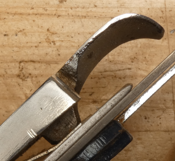
The two videos below show the operation of different lever caps in isolation (original and unaltered from their factory grind). The caps are held securely in the vise and the levers are slowly closed and opened again, thus increasing and decreasing the distance between the main casting and the sprung bar: the part that registers against the cutting iron assembly on a plane. The fine graph paper in the background is only to help notice the difference in the motion of the two bars. The key element to watch for is the distance between the lever cap and the sprung bar. (Just for the record, both lever caps were fully functioning and taken from planes I use in my daily work.)
On the first video, you will notice that the lever does not tighten continually all the way to its horizontal position; rather, it tightens right up to a point, and then loosens a little just as it clicks in place. On the second video, however, the distance from the steel bar keeps increasing until it reaches its ultimate, closed position. This is the same lever cap I tried to tighten in the first video at the top of the page.
A Physical Analysis
Of course, right and wrong are subjective categories, since both lever caps actually work. Having said that, there is a physical basis for making this value judgment. On the first example above, when the lever cap is in the ‘locked’ position, it’s in a state of mechanical equilibrium. This means that it takes a certain amount of physical work to turn the lever past its position of maximum tension and all the way up to the ‘lose’ position. This does not happen when the lever cap just keeps tightening (or ‘levels off’ at its tightest position), as in the second video. I have tried to represent these in the Pressure vs Lever position diagrams below.

Note: The diagram only represents the pressure exerted on the cutting iron assembly. It does not take into account other factors such as friction, which plays an enormous role. In reality, there is (generally) always enough friction between the parts to keep the lever cap from coming loose. This also applies to lever caps with a screw to apply pressure with.
Practical Implications – Confidence, Security, Reliability
A lever cap that has been accurately cast (or milled, or assembled), literally locks tight, and cannot accidentally come loose with a bit of increased vibration (from intense plane use) or with accidental knocks and bumps, as you do every so often in your everyday of working at the bench. Why is this relevant? Knowing this will free you to concentrate on the work at hand as you advance deeper into the craft. You can recognize that you are growing in accuracy as you start take your focus away from the plane and fix your attention on your woodwork. Ultimately, the tool shifts to a subconscious level as you incorporate it, almost literally, as another part of your body. But for this, you need to feel confident that your tools won’t let you down. Your hand planes must be safe to use and reliable in that they will deliver the same performance after every time you stop to sharpen up.
I hope the short (6 second) clip below, showing the same lever cap from the first fail at the top of the page will illustrate the sense of confidence and security you get when a lever cap locks in place as it should.
In Part II, among other related issues, I will discuss the variables of the lever in a more in-depth geometrical analysis, which I hope will be of help if you wish to correct a lever cap for an ideal performance.

Leave a comment