In Part I of this post, I addressed the problem of lever caps that have not been cast/milled correctly. I now wish to discuss the precise factors regarding the shape of the cam on a lever cap that make it work in an ideal manner. My goal is that anyone who detects the same problem in their own lever cap(s) would feel confident enough to make the necessary corrections themselves for a better operation.
As I mentioned previously, a correctly shaped/positioned cam on a lever cap refers to one that results in the lever cap ‘locking’ in a state of mechanical equilibrium when in its closed position. Before getting to that, it’s necessary to analyse the basic basic elements of the cam mechanism. The red lines in the image below show the two faces that register against the steel bar (and cutting iron assembly). Perpendicular to these are two lines that represent the distance from the pivot for both open (green) and closed (yellow) positions. It should be clear that for the lever cap to tighten at all, Dclosed should be longer than Dopen. Thankfully, I have never (and hopefully never will) come across such a lever cap that fails at this elemental test.

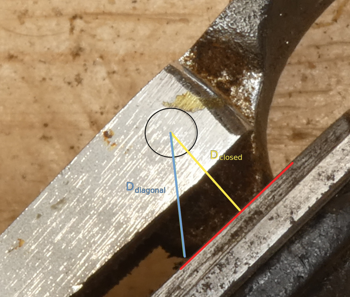
As for what makes the lever cap ‘lock’ in place or simply just ‘tighten’, the two images below of different lever caps will help to identify the key element, and that is where is the longest distance from the pivot. The only two distances in question are Dclosed (already addressed above) and the diagonal distance (Ddiagonal), which is the distance from the pivot point to the rounded corner. In essence, Dclosed must be shorter than Ddiagonal.

As the image above left shows, the distance from the pin to the cutting iron assembly will increase initially as the cam lever is opened for removal, and therefore will first tighten before it loosens completely. That’s the reason why we can say it’s in a state of mechanical equilibrium, or simply mechanically locked. The image to the right, however, indicates that the lever cap will begin to loosen immediately as the lever is turned towards its open position. This means that it’s only friction that holds the lever cap in its closed position. Practical implications are addressed further down.
DIY – A 5 Minutes Fix
If you own, or come across a lever cap that looks like the one above right, you can make the necessary corrections easily with a flat file. All you need to bear in mind is that what you’re aiming for is to create a new plane such that the perpendicular distance to the pivot (Dclosed) will be smaller than Ddiagonal. It really is that simple and it only took me a few minutes (stopping to take some photos) to correct the lever cap in the second image above.
Below is a short clip which I only filmed to show how simple and doable this correction really is and hopefully give readers the confidence they need to roll up their sleeves and do the same on their planes. Further down is a photo with some guidelines to further illustrate what the new grind should look like.

Concluding Remark
I should now say that all of the above is quite irrelevant if you aren’t going to tighten your lever cap enough anyway (which is done by driving the setscrew deeper into the frog). That’s because the whole point of this clever design feature is that it guarantees that the lever cap will lock tight and under no circumstances will it come loose unpredictably.
Why stress the tightness of the lever cap? Well, it’s a question of reliability. As I mentioned in the first part of this post, when you begin to discover the potential of hand tools and you get more and more acquainted with them (through use; not admiration), your attention becomes less divided to a degree where you completely take your mind off the tool at hand to focus solely on the actual work at hand. But this cannot happen unless your tools are reliable; and a plane cannot be reliable if it is easily misset.
I can’t say for sure whether I’ve had a lever cap come loose on a smoothing plane due to the issue I’ve discussed here. However, I know there were several times when a plane gave me no feeling of security upon tightening the lever cap and feeling it could easily fall apart spontaneously. And though I have no experience using smoothing/jack planes with screw-type lever caps -such as the modern Record Irwin or the vintage infills, which don’t lock mechanically either-, I have used No. 78 rebate planes extensively which have the same thumbscrew mechanism for securing the lever caps. And on these, I’ve experienced the lever caps coming loose several times through everyday use, which often includes intense vibrations. So without a doubt, this is a real problem for anyone who wants to pursue the narrow path of hand tool woodworking and discover their full potential. I hope this post serves as encouragement to anyone on that path or wanting to get on it.
Further Note Regarding Variation by Manufacturer
I have yet to find a Stanley plane with a cam shape on the lever cap that hasn’t been cast/ground correctly. I have with some Records, however -the one documented for this post only being the latest. It seems to me very strange that after over 150 years that the idea has been around (see image below), plane manufacturers such as Record would have missed the mark, even if it wasn’t the norm. I can only think it comes down to a demise in the care and pride in the quality of their products.


Leave a reply to John Winter Cancel reply